|
|
|
Review of paper by Chutaro Kato and Yasunori Kawai, Wear of Knife Used for Hand Plane III: The influence of the cap iron Yamagata University, Yamagata, Japan The Japan Wood Research Society Vol. 35, No. 10, p.886-895 (1989)
William Tindall, Steve Elliott, and Frederick Horne Translation by Mia Iwasaki
Professors Kato and Kawai studied the effects of the cap iron (chip breaker) on planing birch wood. This review captures the results and conclusions from their paper that are relevant to hand planing. While the data in this paper were generated on a planing machine, the blade steel and cutting angles are similar to those of hand planing, and it will be shown that the wear patterns at the cutting edge are identical to those observed by Steve Elliott for hand plane blades. This paper is one of several technical papers on the subject of wear of plane blades by these authors. These other papers focus on the effect of different steel alloys and blade coatings on wear (dulling). Three additional publications focus on summarizing the pertinent results of these technical papers for instructors in technical schools teaching hand planing skills. Additionally, a video of planing was made which vividly shows the mechanical interaction of the blade tip and cap iron on the wood fibers for with and against grain planing. We hope to eventually translate and summarize all of the publications by Kato and Kawai. The video is available at these links:
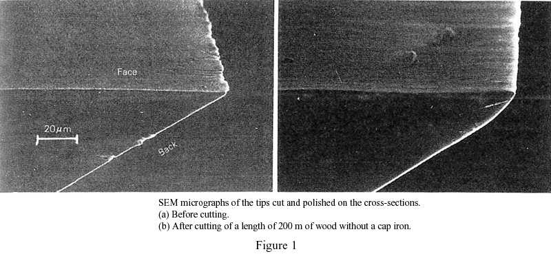
The details of the planing machine and procedure to obtain the SEM images were part of this paper but are not part of this review. The plane blade used in Kato’s experiments was a cutlery steel [Aogami-1 of YSS corresponding to SKS-2 of Japan Industrial Standard (JIS), HRC 65 (Rockwell hardness)]. This steel is the familiar “Blue Steel” used in Japanese planes and chisels. The cap-iron material was carbon steel, S45C of JIS, HRB 78. The cap iron was positioned over the flat or “face” of the blade with the bevel or “back” side of the blade in contact with the wood surface “bevel down” configuration. The blade bevel angle was ground at 30 degrees and the relief angle was 10 degrees. The wood specimens were Betula maximowicziana (Monarch birch) air dried to a moisture content of 10%. The test specimens were 9mm wide (the cutting width), 100mm to 150mm thick and 0.5 m in length. Planing experiments were done both with and against the grain at grain angles relative to the wood surface of -14, -7, 0, +7, +14 degrees (negative values denote cutting against the grain). The shaving thickness was 50µm (0.002”) and the cutting speed was 1m/min, a speed significantly slower than typical manual planing. Between cutting strokes the wood specimen was lowered slightly so that the knife edge did not contact the wood while the specimen was being retracted. Details of the planing machine are described in a separate paper which we have not yet translated. However, it was described that the machine has a load cell to determine the cutting forces parallel and perpendicular to the blade travel. Scanning electron microscopy images of the blade profile were made after 200m (600 feet) of planing. From these images the amount of wear on the top and bottom of the blade was measured. Wear on the cap iron was similarly measured. The objectives of this work were twofold. First was to investigate the nature of the wear on the plane blade and cap iron depending on cap iron leading edge angle, and distance of cap iron leading edge from the cutting tip. It was anticipated that these variables could be optimized to achieve longer edge life through a self sharpening effect of the wear pattern. Second was to investigate the effect of planing with or against the grain on blade wear. Results and Discussion A comparison of a freshly sharpened blade to one that had planed 200m of wood without a cap iron is shown in Figure 1. The tip of an unused blade forms a sharp edge at the intersection of the face and back surfaces. Remains of the burr can be seen on the unused tip. The tip profile of a worn knife after planing 200m is rounded with metal worn away from both the face and back of the blade. The back, or beveled, surface shows a wear profile with a flat surface developed behind the tip at an angle of about 10 degrees, corresponding to the relief angle for the blade in this experiment. This wear is the result of the wood surface rubbing against the beveled side of the blade. It should be noted that this wear negates the relief angle of the blade. It will be shown that this wear surface pushes the blade away from the wood surface.
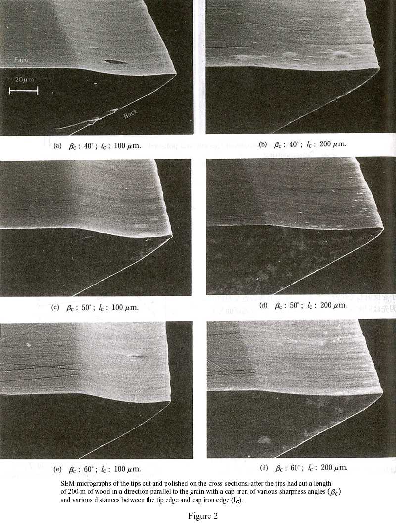
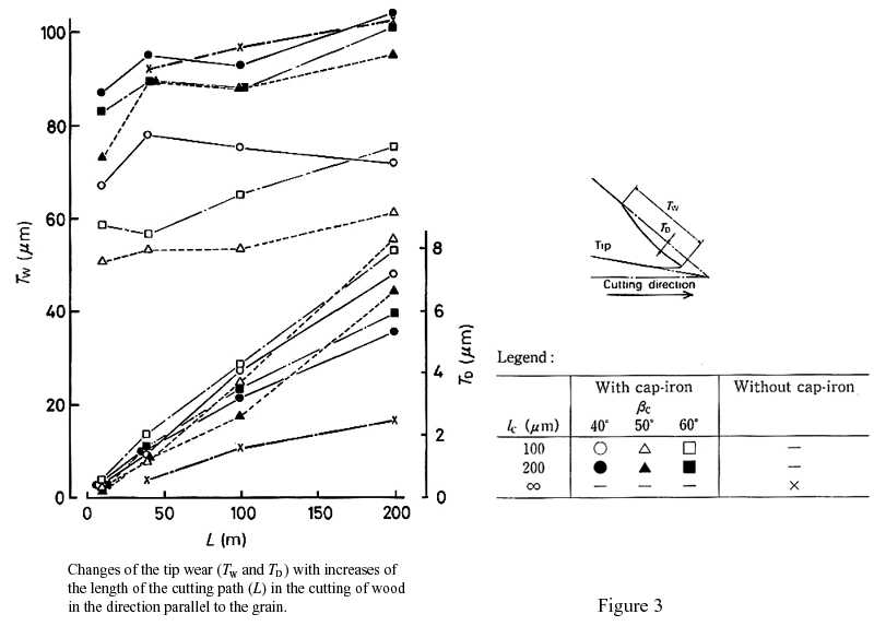
Figure 2 shows the wear on the top side of the blade. A shallow depression wears behind the tip with a depth (TD) of about 1 to 2 µm, and a length (TW) of about 100µm (0.004”). (Refer to Figure 3 for an explanation of TD and TW. In this review we will use the notations of the original paper.) This hollowing of the face is a result of the shavings flowing from the tip and being curled against the blade face by the cap iron. The pressure of these shavings is sufficient to wear away the metal in the region of high shaving pressure between the cap iron edge and the blade tip. Closer placement of the cap iron to the cutting edge and/or increasing the angle of the leading edge of the cap iron increases the shaving deflection (which Kato calls the “cap iron effect”) thereby increasing the pressure of the shaving and, correspondingly, increases the amount of wear on the blade face. Diagrams illustrating the effect of cap iron placement and angle on wear are shown in Figure 3.
Figure 3 shows the effect of these variables on the depth of this wear and its length as a function of planing distance. To summarize Figures 2 and 3, the length of the face wear does not change markedly with distance planed but the depth of this wear increases almost linearly with planing distance. After planing 200m the depth of wear was about 8 microns when the cap iron was 100 microns from the tip, about 6 microns when the cap iron was 200 microns from the tip and only 2 microns when there was no cap iron. These data clearly illustrate the increase in shaving pressure resulting from deflection at the cap iron. The cap iron angle has a small effect on the length and depth of this wear. As could be expected the wear is longer when the cap iron is farther from the cutting tip but the wear always stops short of the cap-iron edge due to relief of the shaving pressure as it is forced away from the blade face by the cap iron.
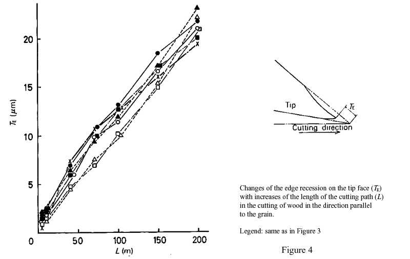
Edge recession is defined as the amount that the blade becomes shortened by wear as diagramed in Figure 4.
Recession increases linearly with planing distance in the range of 0 to 200m. One might speculate that the duller the knife became, the faster it would wear, but these data do not support this conjecture. After 200m about 20 to 25 microns (0.001”) is worn from the tip depending on the placement of the cap iron and its angle. Perhaps surprisingly, there is less wear when the cap iron is closer to the tip, but this effect is not great given that the total range of the wear is 20 to 25 microns in these experiments. Perhaps the splitting action of the cap iron reduces abrasion at the tip such that more splitting action (closer cap iron) results in less tip recession.
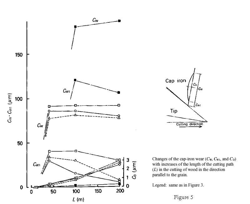
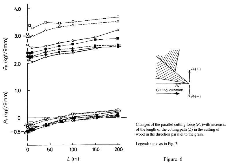
Measurements were also made on the length and depth of wear on the cap iron (Figure 5). As expected, conditions that resulted in a more wedging action of the cap iron (closer to the tip and/or higher angle) resulted in more wear, presumably as a result of more pressure from the exiting shavings. A conclusion from these observations is that blade face wear and cap iron wear reflect the amount of force the cap iron is exerting to deflect the shaving flowing over the blade face and cap iron, up to a point. Even under the most mild cap iron effect (200 micron (.008”) distance from tip and 40 degrees) the depth of the wear on the blade face was twice that for no cap iron, illustrating the significant effect of the cap iron even under these conditions. If the deflection of the shaving is too great (what Kato calls the cap iron effect) the mechanics of forming the shaving changes resulting in a compressed or wrinkled shaving structure, likely due to the cap iron compression forces crushing the wood fibers. The planing machine included load cells to measure the forces on the blade perpendicular and parallel to the direction of planing. These data are summarized in Figure 6.
First, considering the force parallel to the planing direction, the initial force with a freshly sharpened blade and the cap iron at 200 microns (0.008”) was in the range of 2.2 to 2.3 kg(about five pounds) with this force slightly increasing in this range with increasing cap iron angle. The initial force with the cap iron at 100 microns ranged from 2.5 to 3.5 kg and again the force increased in this range with increasing cap iron angle. The trend of these results is what one would expect from the cap iron forcing the flowing shavings to bend over it. In all cases this force remained nearly constant for about 10m and then in most cases increased approximately linearly with planing distance up to 200m. The increase in this planing force no doubt is a result of dulling the blade tip. The data with no cap iron tracked the 40 degree data with the cap iron at 200 microns. From these data we can conclude that significant dulling/wear of the edge begins at about 10m (30’) of lumber planed as evidenced by the increase in planing force. The data on the force perpendicular to the direction of planing are much more provocative. In all cases, the initial force with a freshly sharpened blade is directed into the planed surface. Initially this force pulls the sharp blade into the wood. With the cap iron at 200 microns the force pulling the freshly sharpened blade into the surface was twice (0.5 vs. 0.25 kg) that for 100 microns. The cap iron angle showed little effect. But, as wear developed on the blade (more feet of wood planed) the perpendicular planing force reversed direction in the range of 50 to 100m planed, pushing the dulled blade away from the wood. This reversal of the perpendicular force is due to loss of relief angle due to the flat spot worn on the bevel (back) side of the blade. Conclusion from Part 1 data 1. Under the conditions studied [cap iron settings between 100 and 200 μm (0.004 to 0.008”) and angles of 40 to 60 degrees] the cap iron deflects the shavings flowing up the blade face (“cap iron effect”). These bent shavings are forced against the blade face. This pressure is concentrated between the leading edge of the cap iron and the tip of the blade. The cap iron and blade wear (loss of metal) are a result of friction generated by this pressure. Factors that increase this force, cap iron position and cap iron leading edge angle, lead to more pressure and more wear. Hence, this wear is a reflection of, and can be a measure of, the cap iron working to deflect the shaving (“cap iron effect”). The amount of wear increases approximately linearly with distance planed. 2. From the data for wear behind the blade tip with and without cap iron it was shown that there is still a substantial cap iron effect at 200 microns (0.008”). 3. The bottom (bevel) of the blade rubs along the planed surface. This motion leads to abrasion of the bottom surface to produce a flat wear surface behind the tip. The amount (length) of this wear increases approximately linearly with planed distance. 4. The tip of the blade is worn away in an approximately linear fashion as a function of distance planed (about 0.001” in 600’ of wood planed). Cap iron position and angle have but a small effect on the amount of this wear. 5. The wear at the tip does not result in as much blunting of the edge as might be expected from this loss of material because wear at the top and bottom of the blade lead to some self-sharpening of the blade (see Figure 2). 6. As a result of self sharpening the increase in force to push the blade forward does not dramatically increase with distance planed. 7. The amount of force to push the plane forward increases in proportion to the force exerted by the cap iron on the exiting shaving (“cap iron effect”). 8. The force perpendicular to the direction of planing reverses with distance planed. Initially the blade is pulled into the wood surface, but as the blade gets dull, in particular that the flat spot develops on the back (beveled side) of the blade, the blade is pushed away from the surface. In hand planing these forces would initially pull the plane into the planed surface, but with dulling, the plane would be pushed away from the surface. 9. The best wear profile, resulting in self sharpening, was found at a cap iron distance of 100 microns (0.004”) and an angle of 50 degrees. The most shallow wear on the blade face was at a cap iron distance of 200 microns and an angle of 50 or 60 degrees.
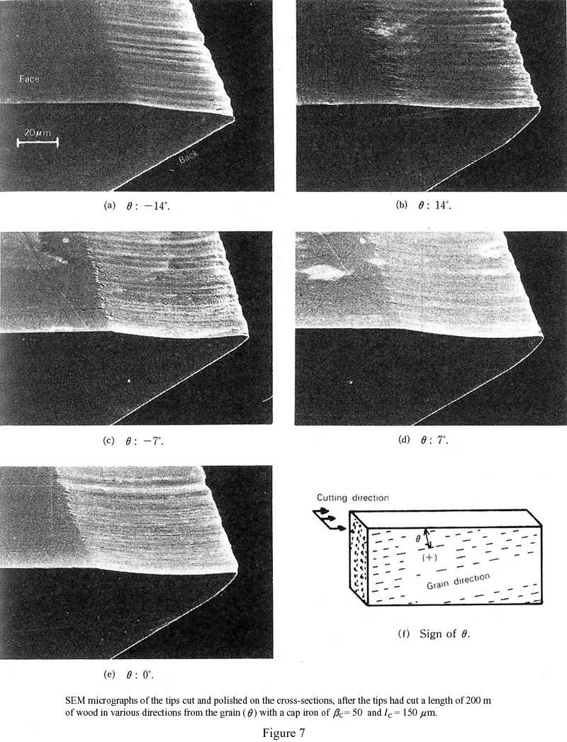
In part 2 of this paper the effect of grain orientation on wear was studied. Based on considerations of Conclusion 9, the cap iron was set at an in-between value of 150 microns and the angle was 50 degrees for these studies. Grain angles (angle of the grain relative to wood surface) were studied at -14, -7, 0, +7 and +14 degrees. Minus angles indicate against the grain planing. These angles include the typical range of grain orientation found in sawn lumber. Grain angle has a profound effect on the profile and amount of blade wear at these cap iron conditions. The wear profiles for this cap iron configuration at different grain orientations are shown in Figure 7.
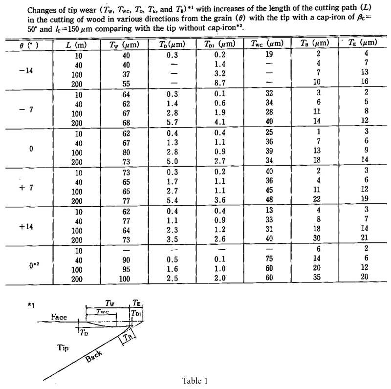
For grain angles from -7 through +7 degrees, the shaving has a large bending stiffness. The shaving flowing over the blade face applies force on the blade face and wears out a hollow between the cap iron and the tip as described in Part 1. The wear profile and amount is essentially the same within the +7 to -7 degree range. However, for grain angles of +14 or -14 degrees the bending stiffness of the shaving is smaller resulting in the force of the shaving being concentrated near the blade’s tip. As a result the wear is concentrated at the blade tip and instead of hollowing out the blade face a flatter wear face is developed. At -14 degrees (against the grain) the blade tip works as a lever on the wood fibers. In this case the fibers are levered up by the blade tip which results in the wood fracturing ahead of the blade tip instead of the tip simply slicing through the fibers as is the case with with-the- grain planing. This effect is clearly seen in the Kato-Kawai planing video. Because the grain is angling into the planed surface, these fractures penetrate below the planed surface resulting in what we commonly refer to as “torn grain.” While it is not discussed in this publication, other work by Kato and Kawai and others show that the solution to mitigating torn grain is to apply a perpendicular force into the planed surface ahead of the blade tip and/or to apply less levering force by raising the blade angle and employing a sharp blade. One of the ways to apply this force is by optimum cap iron placement coupled with increasing the leading edge angle of the cap iron to 80 degrees, as can be clearly seen in the video. This levering action results in greater wear near the blade tip. The result is a worn tip comprised of a nearly flat secondary bevel on the blade face as though the blade had been ground to produce this second bevel (see picture in Figure 7). The secondary bevel produced by this wear substantially increases the blade’s effective bevel angle at the tip. In contrast, at +14 degrees the wood fractures ahead of and above the blade tip, and therefore above the planed surface. In this case the shaving slides across a longer length of the blade face. Again, a relatively flat wear surface is produced but one covering a greater area behind the tip than in the -14 degree case. Because the wear is spread over a greater distance behind the tip the effective bevel angle is not changed nearly as much as in the -14 degree case. Turning to the wear on the back or beveled side of the blade, for a given distance planed, the length of the flat spot worn from rubbing on the planed surface increases with increasing grain angle. According to Kato the fracture pattern of the wood at the blade tip leads to a less abrasive wood surface behind the tip when the grain angle is less. At negative angles (against the grain) the wood fibers levered up by the blade tip spring back behind the blade tip. As seen in the video, at times there is no wood rubbing just behind the blade tip with against-the-grain planing. The torn wood fibers that were levered up and then severed have sprung back to create a torn grain surface that lies below the blade tip! In contrast, at positive grain angles (with the grain) the wood fracture occurs above the surface of the planed wood resulting in compressed fibers behind the tip. These fibers spring back and result in more pressure and hence more wear on the back of the blade. The length of this wear increases approximately linearly with distance planed. These phenomena can be readily seen in the planing video referenced in the introduction. Under the cap iron conditions used in this work the difference in wear is remarkable with and without a cap iron as seen in Table 1. After a planed distance of 200m the length of the flat spot worn on the back of the blade without a cap iron is twice that for the case with a cap iron set at 150 microns. Similarly, recession of the blade tip is a third greater without a cap iron. However, these data are in conflict with the data in Figure 4 which shows the least tip recession in the case with no cap iron after 200m of planing. The author’s explanation of these results in terms of the mechanics of shaving formation was unclear. When cutting against the grain, the combination of the self-sharpening effect and the lessened force from the cut fibers on the bottom of the blade leads to less rapid development of the flat spot on the blade bevel behind the tip. Conversely, when cutting with the grain, there is less self-sharpening effect and more force from the cut fibers below the blade leads to more rapid development of this flat spot. In summary, an analysis how the shaving applies force, and hence abrasion, to the blade predicts the wear profiles and amounts of wear observed. Conversely, the wear on the blade reflects the distribution of these forces on the blade and cap iron.
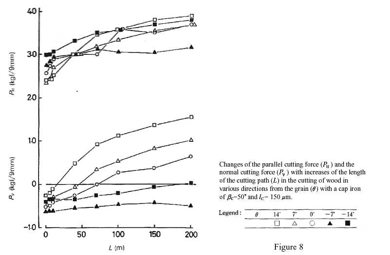
Referring to Figure 8, the force to push the blade through the wood ranged from 2.2 to 3.0 Kg for the 9mm wide wood test specimen, with against-the- grain forces being greater than with-the-grain forces. This force increases with distance planed with the increase greater for with-grain orientation. The increase in this force after 200m ranged from 1.5 kg for 14 degrees to 1.0 kg for minus 14 degrees. The details of the wear pattern and mechanics of chip formation interact to cause the modest differences in this force observed. With the exception of the -14 degree grain experiment the force normal to the plane of the board began negative (blade pulled into the surface) and trended to positive values with distance planed. Kato explained the nearly constant negative force for the -14 degree grain was a result of the wear profile developed in this experiment resulting in an effective bevel angle increasing from 30 to 38 degrees.
Conclusions Part 2 Differences in the angle of the grain to the direction of blade travel result in profound differences in the forces of the wood shaving on the face of the blade and the forces of the planed surface on the bottom of the blade. These differences result in significant differences in the wear patterns observed and the amount of wear observed as a function of distance planed. Against the grain planing can result in wood fracture ahead of and below the blade tip surface, with fracture propagating into the planed surface. This result is observed at a grain orientation of -14 degrees and it results in a substantially different wear profile as well as different parallel and perpendicular planing forces than observed for other grain orientations.
References
|
|
[Home] [Summary of Results] [Testing Procedure] [Chipbreaking] [Chipbreaker Tests] [Chipbreaker Study] [A Controlled Test] [Review of Cap Iron Study] [Cap Iron Study by Kees van der Heiden] [Mechanics of Chipbreakers] [Cutting Angles] [Shaving Formation] [Tuning Infill Planes] [Links & References] [Contact] [Site Map] |
